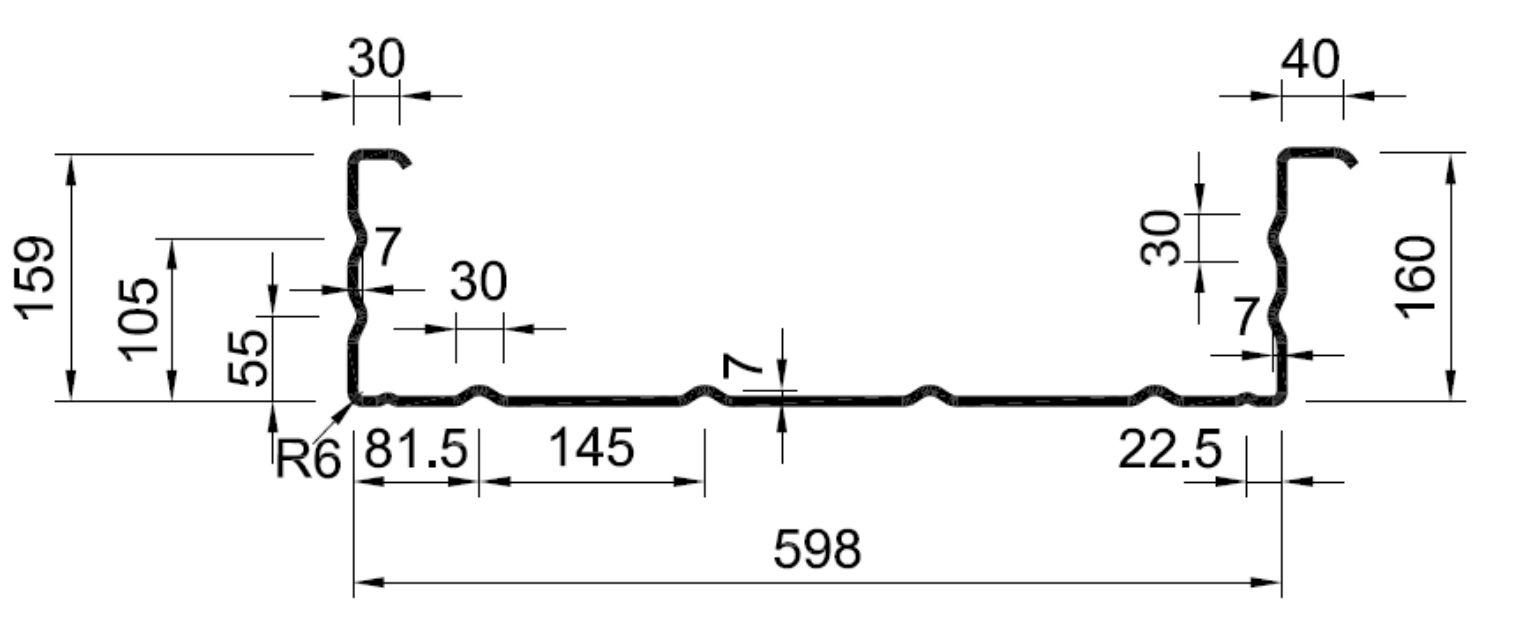
 Hacierba 160/600 SR
1 Section properties of the liner tray in compliance with
baustatische Typenprüfung Bescheid Nr. T18-013
Hacierba 160/600 SR
Nominal thickness = 0.88 mm Design thickness = 0.84 mm
Yield strength fy,k = 320 N/mm^2
Second moment of area Ief = 376.4 cm^4/m
Characteristic capacity of the liner tray for UDL downwards
Width of the end support bA = 40 mm Width of the internal support bB = 100 mm eps = 1
Mc,Rk,F = 6.96 kNm/m Rw,Rk,A = 10.15 kN/m Vw,Rk = 23.03 kN/m
M0,Rk,B = 14.08 kNm/m R0,Rk,B = 30.69 kN/m Mc,Rk,B = 8.54 kNm/m Rw,Rk,B = 18.63 kN/m
Width of the end support bA = 40 mm Width of the internal support bB = 300 mm eps = 1
Mc,Rk,F = 6.96 kNm/m Rw,Rk,A = 10.15 kN/m Vw,Rk = 23.03 kN/m
M0,Rk,B = 12.38 kNm/m R0,Rk,B = 77.75 kN/m Mc,Rk,B = 9.72 kNm/m Rw,Rk,B = 25.62 kN/m
Characteristic capacity of the liner tray for UDL upwards
Mc,Rk,F = 9.08 kNm/m Rw,Rk,A = 10.15 kN/m Vw,Rk = 23.03 kN/m
M0,Rk,B = 11.73 kNm/m R0,Rk,B = 39.53 kN/m Mc,Rk,B = 8.32 kNm/m Rw,Rk,B = 19.92 kN/m
Symbols (elements of capacity)
Mc,Rk,F Sagging moment capacity maxMR,Rk residual moment capacity
Rw,Rk,A External support capacity Vw,Rk Shear force
M0,Rk,B Hogging moment capacity under the assumption of no shear force
R0,Rk,B Internal support capacity under the assumption of no moment
Mc,Rk,B Hogging moment capacity Rw,Rk,B Internal support capacity
eps 1: linear interaction for M and R 2: quadratic interaction for M and R
2 Structural system and loads
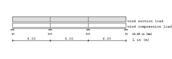
Loads Type 1: Trapezodial distributed load from a to a+b
Type 2: Pointload at a
Load Type q1 Start q2 Length
[kN/m^2] [m] [kN/m^2] [m]
wd Wind compression load 1 0.400 0.000 0.400 6.000
1 0.400 6.000 0.400 6.000
1 0.400 12.000 0.400 6.000
ws Wind suction load 1 -0.480 0.000 -0.480 6.000
1 -0.480 6.000 -0.480 6.000
1 -0.480 12.000 -0.480 6.000
3 Design of liner trays in compliance with Building Standard "EN 1993-1-3 (EC3)"
3.1 Ultimate limit state (ULS) elastic-elastic
3.1.1 Sagging moment gamma-F,G= 1.35 gamma-F,Q= 1.50 gamma-M= 1.10
Load combination Bay MEd Mc,Rd,F Utilization
[-] [-] [kNm/m] [kNm/m] [-]
1.50*Wd 1 1.728 < 6.327 0.273
2 0.540 < 6.327 0.085
3 1.728 < 6.327 0.273
1.50*Ws 1 -2.074 < 8.255 0.251
2 -0.648 < 8.255 0.078
3 -2.074 < 8.255 0.251
3.1.2 Reaction at end support gamma-F,G= 1.35 gamma-F,Q= 1.50 gamma-M= 1.10
Load combination Support FEd Rw,Rd,A Utilization
[-] [kN/m] [kN/m] [-]
1.50*Wd 1 1.440 < 9.227 0.156
4 1.440 < 9.227 0.156
1.50*Ws 1 -1.728 < 9.227 0.187
4 -1.728 < 9.227 0.187
3.1.3 Shear force at internal support gamma-F,G= 1.35 gamma-F,Q= 1.50 gamma-M= 1.10
Load combination Support VEd Vw,Rd bv Utiliz.
[-] [kN/m] [kN/m] [-] [-]
1.50*Wd 2 -2.160 < 20.936 0.091 0.103
1.50*Wd 3 2.160 < 20.936 0.091 0.103
1.50*Ws 2 2.592 < 20.936 0.091 0.124
1.50*Ws 3 -2.592 < 20.936 0.091 0.124
3.1.3 Reaction at internal support gamma-F,G= 1.35 gamma-F,Q= 1.50 gamma-M= 1.10
Load combination Support FEd Rw,Rd,B Utilization
[-] [kN/m] [kN/m] [-]
1.50*Wd 2 3.960 < 23.291 0.170
1.50*Wd 3 3.960 < 23.291 0.170
1.50*Ws 2 -4.752 < 18.109 0.262
1.50*Ws 3 -4.752 < 18.109 0.262
3.1.4 Hogging moment gamma-F,G= 1.35 gamma-F,Q= 1.50 gamma-M= 1.10
Load combination Support MEd Mc,Rd,B Utilization
[-] [kNm/m] [kNm/m] [-]
1.50*Wd 2 -2.160 < 8.836 0.244
3 -2.160 < 8.836 0.244
1.50*Ws 2 2.592 < 7.564 0.343
3 2.592 < 7.564 0.343
3.1.5 Combined check for bending and reaction gamma-F,G=1.35 gamma-F,Q=1.50 gamma-M=1.10
Load combination Support MEd/M0,Rd,B + (FEd/R0,Rd,B)^eps Utiliz.
[-] [-] [-] [-]
1.50*Wd 2 0.192 + 0.056 0.248
3 0.192 + 0.056 0.248
1.50*Ws 2 0.243 + 0.132 0.375
3 0.243 + 0.132 0.375
3.1.5 Combined check for bending and shear gamma-F,G=1.35 gamma-F,Q=1.50 gamma-M=1.10
Load combination Support MEd/Mc,Rd,B + (2*VEd/V,Rd,B-1)^2
[-] [-] [-] [-]
1.50*Wd Design not necessary!
1.50*Ws Design not necessary!
3.2 Serviceability limit state (SLS) elastic - elastic
3.2.1 Deflection gamma-F,G= 1.00 gamma-F,Q= 1.00 gamma-M= 1.00
Load combination Bay f Perm. f, L/150 Utilization
[-] [-] [cm] [cm] [-]
wd, Wind compression load 1 0.451 < 4.000 0.113
2 0.034 < 4.000 0.009
3 0.451 < 4.000 0.113
ws, Wind suction load 1 -0.751 < 4.000 0.188
2 -0.057 < 4.000 0.014
3 -0.751 < 4.000 0.188
The design of the liner tray is ok. The load capacities of the liner trays can have large
differences from manufacturer to manufacturer. Therefore, it is important that the liner tray
listed herein is actually installed on-site during construction.
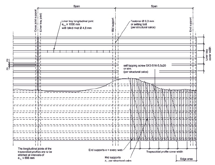
The upper chords of the liner trays must be stitched to the trapezoidal sheets at intervals
of al <= 621 mm centres.
The liner tray webs have to be stitched to each other in the longitudinal joints using blind
rivets or equally suitable alternative fixings at intervals of ek,l <= 1000 mm, at the same
time the longitudinal joints of the trapezoidal sheets must be stitched together at intervals
of et,l <= 666 mm.
The minimum requirements of the external shell are to be taken from the certification
baustatische Typenprüfung Bescheid Nr. T18-013. The proof of the structural integrity of
the external shell is not part of these calculations.
4 Design of connection elements
4.1 Connection of liner tray to substructure
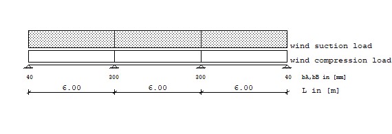
Loads Type 1: Trapezodial distributed load from a to a+b
Type 2: Pointload at a
Load Type q1 Start q2 Length
[kN/m^2] [m] [kN/m^2] [m]
Ws, wind suction load 1 -0.600 0.000 -0.600 6.000
1 -0.600 6.000 -0.600 6.000
1 -0.600 12.000 -0.600 6.000
Characteristic forces of connection elements:
End support Fz,k= 3.600 kN NR,k,red= 0.7*NR,k= 2.520 kN VR,k= 3.600 kN
Internal support Fz,k= 3.600 kN NR,k,red= 0.7*NR,k= 2.520 kN VR,k= 3.600 kN
Shear and tension capacity of the connection elements, gamma= 1.33:
End support Fz,d= 1.895 kN VR,d= 2.707 kN
Internal support Fz,d= 1.895 kN VR,d= 2.707 kN
Reaction at the support, load case excluding safety factors:
Support Rv,k(wd) Rv,k(ws) Rv,k(option.) Descript. Rh,k(option.) Descript.
[-] [kN/m] [kN/m] [kN/m] [-] [kN/m] [-]
1 0.960 -1.440 0.000 0.000
2 2.640 -3.960 0.000 0.000
3 2.640 -3.960 0.000 0.000
4 0.960 -1.440 0.000 0.000
Reaction at support for load combinations:
Load combination Support Vertical Horizontal
[-] [kN/m] [kN/m]
1.5*Ws 1 -2.160 0.000
1.5*Ws 2 -5.940 0.000
1.5*Ws 3 -5.940 0.000
1.5*Ws 4 -2.160 0.000
Design check for connecting elements, module width bR = 600 mm
Support nVerb NE,d NR,d VE,d VR,d Utilization
[-] [-] [kN] [kN] [kN] [kN] [-]
1 2 0.648 < 1.895 0.000 < 2.707 0.342
2 2 1.782 < 1.895 0.000 < 2.707 0.940
3 2 1.782 < 1.895 0.000 < 2.707 0.940
4 2 0.648 < 1.895 0.000 < 2.707 0.342
Rv, Rh : Reaction at support caused by load combinations
nVerb : Number of connecting elements
bR : Module width
NE,d : Applied tension force in the connecting element = Rv·1/nVerb·bR·(-1)
NR,d : Tension capacity in the connecting element
VE,d : Applied shear force in the connecting element = Rh·1/nVerb·bR
VR,d : Shear capacity in the connecting element
4.2 Liner tray longitudinal joint
The liner tray webs have to be stitched to each other in the longitudinal joints using
blind rivets or equally suitable alternative fixings at intervals of ek,l <= 1000 mm.
4.3 Connection of trapezoidal sheets to the upper chords of the liner trays
The upper chords of the liner trays must be stitched to the trapezoidal sheets at inter-
vals of al <= 732 mm centres. The structural proof of these fixings is not part of this cal-
culation and must be provided separately when dimensioning the trapezoidal sheeting.
4.4 Example of a connection plan for a liner tray wall
5 Summary of design
Ultimate limit state (ULS) elastic-elastic
Mc,Rk,f 27.3 %
Rw,Rk,A 18.7 %
Rw,Rk,B 26.2 %
Vw,Rk 12.4 %
Mc,Rk,B 34.3 %
M-R 37.5 %
Serviceability limit state (SLS) elastic - elastic
Rw,Rk,B -
Mc,Rk,B -
M-R -
f 18.8 %