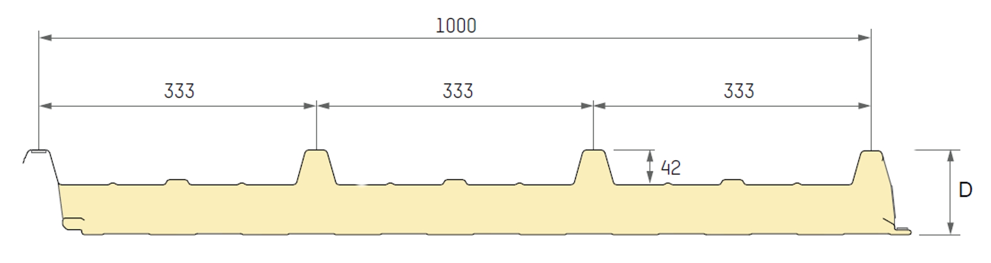
1 Panel specification Romakowski Dämmpaneel Typ D TL 162 according German approval Z-10.4-549
Cross section values per [m] of module width
Outer sheet type T
Nominal thickness t_nom = 0.60 mm
Design thickness t_d = 0.54 mm
Cross sectional area A = 6.62 cm^2/m
Section modulus W = 3.4 cm^3/m
Moment of inertia I = 11.8 cm^4/m
Bending stiffness B = 24.7 kNm^2/m
Inner sheet type L
Nominal thickness t_nom = 0.50 mm
Design thickness t_d = 0.44 mm
Cross sectional area A = 4.40 cm^2/m
Sandwich panel Design values for wrinkling stress
D=16.20 cm a=12.70 cm a1= 5.07 cm a2= 7.63 cm
Outer sheet type T
Section modulus W_outside = 84.04 cm^3/m Serviceability limit state (SLS)
W_inside = 55.86 cm^3/m T <= 20°C T > 20°C
Moment of inertia I = 426.0 cm^4/m Sigma_w, field 320.0 MPa 320.0 MPa
Bending stiffness B = 894.6 kNm^2/m Sigma_w, support 320.0 MPa 320.0 MPa
Shear stiffness S = 431.6 kN/m
Ultimate limit state (ULS)
T <= 20°C T > 20°C
Sigma_w, field 320.0 MPa 320.0 MPa
Sigma_w, support 320.0 MPa 320.0 MPa
Material parameters
Steel cover sheets Inner sheet type L
Modulus of elasticity E = 210000 MPa Serviceability limit state (SLS)
Yield strength fy = 320 MPa T <= 20°C T > 20°C
Sigma_w, field 148.0 MPa 148.0 MPa
Sigma_w, support 134.0 MPa 134.0 MPa
Foam core PUR
Shear modulus Gs = 3.40 MPa Ultimate limit state (ULS)
Shear strength fcv = 0.090 MPa T <= 20°C T > 20°C
Compression strength fcc = 0.100 MPa Sigma_w, field 148.0 MPa 148.0 MPa
Creep coefficients phi-G = 7.0 Sigma_w, support 134.0 MPa 134.0 MPa
phi-Q = 1.8
2 Structural frame and loads
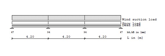
Loads Type 1: Trapezodial distributed load from a to a+b
Type 2: Pointload at a
Type 3: Temperature difference over full girder length
Dead load, snow, wind Load Type q1 Start q2 Length
[kN/m^2] [m] [kN/m^2] [m]
g dead load 1 0.157 0.000 0.157 4.200
1 0.157 4.200 0.157 4.200
1 0.157 8.400 0.157 4.200
s snow load 1 1.000 0.000 1.000 4.200
1 1.000 4.200 1.000 4.200
1 1.000 8.400 1.000 4.200
ws wind suction load 1 -1.750 0.000 -1.750 4.200
1 -1.750 4.200 -1.750 4.200
1 -1.750 8.400 -1.750 4.200
Temperature Ultimate limit state (ULS) dT1
[°C]
tsu,uls temperature, summer 3 55.000
twi,uls temperature, winter - with snow - 3 -20.000
twi,uls temperature, winter 3 -40.000
Temperature Service limit state (SLS) dT1
[°C]
tsu,sls temperature, summer 3 55.000
twi,sls temperature, winter - with snow - 3 -20.000
twi,sls temperature, winter 3 -40.000
3 Initial forces and deflections
3.1 Ultimate limit state (ULS), a serie of simply supported panels
Field/Supp. Mf,face Mf,sand f Mst,face Mst,sand Qsand V
1 0.018 0.329 0.143 0.000 0.000 0.284 0.330 g
2 0.018 0.329 0.143 0.000 0.000 0.284 0.659
3 0.018 0.329 0.143 0.000 0.000 0.284 0.659
4 0.000 0.000 0.284 0.330
1 0.113 2.093 0.913 0.000 0.000 1.810 2.100 s
2 0.113 2.093 0.913 0.000 0.000 1.810 4.200
3 0.113 2.092 0.913 0.000 0.000 1.810 4.200
4 0.000 0.000 1.810 2.100
1 -0.197 -3.662 -1.597 0.000 0.000 3.167 -3.675 ws
2 -0.197 -3.662 -1.597 0.000 0.000 3.167 -7.350
3 -0.197 -3.662 -1.597 0.000 0.000 3.167 -7.350
4 0.000 0.000 3.167 -3.675
1 -0.125 0.125 -1.087 0.000 0.000 0.434 0.000 tsu
2 -0.125 0.125 -1.087 0.000 0.000 0.434 0.000
3 -0.125 0.125 -1.087 0.000 0.000 0.438 0.000
4 0.000 0.000 0.438 0.000
1 0.045 -0.045 0.395 0.000 0.000 0.158 0.000 twis
2 0.045 -0.045 0.395 0.000 0.000 0.158 0.000
3 0.045 -0.045 0.395 0.000 0.000 0.159 0.000
4 0.000 0.000 0.159 0.000
1 0.091 -0.091 0.791 0.000 0.000 0.316 0.000 twi
2 0.091 -0.091 0.791 0.000 0.000 0.316 0.000
3 0.091 -0.091 0.791 0.000 0.000 0.318 0.000
4 0.000 0.000 0.318 0.000
1 0.071 0.275 0.565 0.000 0.000 0.219 0.330 g,cr
2 0.071 0.275 0.565 0.000 0.000 0.219 0.659
3 0.071 0.275 0.565 0.000 0.000 0.219 0.659
4 0.000 0.000 0.219 0.330
1 0.209 1.996 1.701 0.000 0.000 1.657 2.100 s,cr
2 0.209 1.996 1.701 0.000 0.000 1.657 4.200
3 0.209 1.996 1.701 0.000 0.000 1.657 4.200
4 0.000 0.000 1.657 2.100
3.2 Serviceability limit state (SLS), multi-span panel
Field/Supp. Mf,face Mf,sand f Mst,face Mst,sand Qsand V
1 0.015 0.217 0.105 0.000 0.000 0.226 0.270 g
2 0.011 0.083 0.066 -0.080 -0.172 0.087 0.720
3 0.015 0.217 0.105 -0.080 -0.172 0.085 0.720
4 0.000 0.000 0.226 0.270
1 0.093 1.381 0.670 0.000 0.000 1.437 1.717 s
2 0.069 0.527 0.421 -0.512 -1.097 0.553 4.583
3 0.093 1.381 0.670 -0.512 -1.097 0.539 4.583
4 0.000 0.000 1.437 1.717
1 -0.162 -2.416 -1.173 0.000 0.000 2.514 -3.004 ws
2 -0.121 -0.921 -0.736 0.896 1.920 0.967 -8.021
3 -0.163 -2.416 -1.173 0.896 1.920 0.943 -8.021
4 0.000 0.000 2.515 -3.004
1 -0.097 4.767 -0.515 0.000 0.000 1.571 1.168 tsu
2 0.007 4.900 0.092 0.140 4.767 0.674 -1.168
3 -0.097 4.767 -0.515 0.140 4.767 0.670 -1.168
4 0.000 0.000 1.574 1.168
1 0.035 -1.733 0.187 0.000 0.000 0.571 -0.425 twis
2 -0.003 -1.782 -0.033 -0.051 -1.733 0.245 0.425
3 0.035 -1.733 0.187 -0.051 -1.733 0.244 0.425
4 0.000 0.000 0.573 -0.425
1 0.070 -3.467 0.374 0.000 0.000 1.142 -0.850 twi
2 -0.005 -3.564 -0.067 -0.102 -3.467 0.490 0.850
3 0.070 -3.467 0.374 -0.102 -3.467 0.487 0.850
4 0.000 0.000 1.145 -0.850
1 0.064 0.181 0.410 0.000 0.000 0.169 0.277 g,cr
2 0.051 0.075 0.242 -0.169 -0.051 0.042 0.712
3 0.064 0.181 0.410 -0.169 -0.051 0.041 0.712
4 0.000 0.000 0.169 0.277
1 0.188 1.338 1.309 0.000 0.000 1.314 1.748 s,cr
2 0.162 0.563 0.895 -0.761 -0.719 0.382 4.552
3 0.188 1.338 1.309 -0.761 -0.719 0.373 4.552
4 0.000 0.000 1.314 1.748
1 -0.329 -2.341 -2.291 0.000 0.000 2.299 -3.058 ws,cr
2 -0.283 -0.985 -1.567 1.332 1.259 0.668 -7.967
3 -0.330 -2.342 -2.291 1.332 1.259 0.653 -7.967
4 0.000 0.000 2.300 -3.058
4 Design of sandwich panel
4.1 Ultimate limit state (ULS), without creep
4.1.1 Limited normal stresses in face layers: Bay
gamma_m,sigma_w(outer shell)= 1.10 gamma_m,sigma_w(inner shell)= 1.12 gamma_m,fy= 1.10
Load combination Bay Sigma,o Sigma_w,o util. Sigma,i Sigma_w,i Util.
[-] [-] [MPa] [MPa] [-] [MPa] [MPa] [-]
1.0*G+1.5*(Ws+0.6*Twi) 1 119.9 < 290.9 0.412 -93.9 < 132.1 0.711
2 119.9 < 290.9 0.412 -93.9 < 132.1 0.711
3 119.9 < 290.9 0.412 -93.9 < 132.1 0.711
4.1.2 Limited shear stress in the core material: gamma_m= 1.30
Load combination Support Tau fcv Util.
[-] [-] [MPa] [MPa] [-]
1.0*G+1.5*(Ws+0.6*Twi) 1 0.037 < 0.069 0.541
2 0.037 < 0.069 0.541
3 0.037 < 0.069 0.541
4 0.037 < 0.069 0.541
4.1.3 Compression stresses at support, support widths: gamma_m= 1.30
Load combination Support Al Req b Exist b Util.
[-] [kN/m] [mm] [mm] [-]
1.35*G+1.5*S 1 3.595 46.7 ~ 46.7 1.001
2 7.190 93.5 < 93.5 1.000
3 7.190 93.5 < 93.5 1.000
4 3.595 46.7 ~ 46.7 1.001
4.2 Ultimate limit state (ULS), with creep
4.2.1 Limited normal stresses in face layers: Bay
gamma_m,sigma_w(outer shell)= 1.10 gamma_m,sigma_w(inner shell)= 1.12 gamma_m,fy= 1.10
Load combination Bay Sigma,o Sigma_w,o util. Sigma,i Sigma_w,i Util.
[-] [-] [MPa] [MPa] [-] [MPa] [MPa] [-]
1.35*G+1.5*(S+TwiS) 1 -160.4 < 290.9 0.551 60.2 < 290.9 0.207
2 -160.4 < 290.9 0.551 60.2 < 290.9 0.207
3 -160.4 < 290.9 0.551 60.2 < 290.9 0.207
4.2.2 Limited shear stress in the core material: gamma_m= 1.30
Load combination Support Tau fcv Util.
[-] [-] [MPa] [MPa] [-]
1.35*G+1.5*S 1 0.023 < 0.028 0.819
2 0.023 < 0.028 0.819
3 0.023 < 0.028 0.819
4 0.023 < 0.028 0.819
4.3 Serviceability limit state (SLS), without creep
4.3.1 Limited normal stresses in face layers: Bay
gamma_m,sigma_w(outer shell)= 1.00 gamma_m,sigma_w(inner shell)= 1.02 gamma_m,fy= 1.00
Load combination Bay Sigma,o Sigma_w,o util. Sigma,i Sigma_w,i Util.
[-] [-] [MPa] [MPa] [-] [MPa] [MPa] [-]
1.0*(G+0.6*Ws+Twi) 1 49.6 < 320.0 0.155 -56.2 < 145.1 0.387
2 67.6 < 320.0 0.211 -72.2 < 145.1 0.498
3 49.6 < 320.0 0.155 -56.2 < 145.1 0.387
4.3.2 Limited normal stresses in face layers: Support
gamma_m,sigma_w(outer shell)= 1.00 gamma_m,sigma_w(inner shell)= 1.02 gamma_m,fy= 1.00
Load combination Support Sigma,o Sigma_w,o Util. Sigma,i Sigma_w,i Util.
[-] [-] [MPa] [MPa] [-] [MPa] [MPa] [-]
1.0*(G+Ws+0.6*Tsu) 2 -318.6 < 320.0 0.996 82.5 < 320.0 0.258
3 -318.7 < 320.0 0.996 82.5 < 320.0 0.258
4.3.3 Limited shear stress in the core material: gamma_m= 1.08
Load combination Support Tau fcv Util.
[-] [-] [MPa] [MPa] [-]
1.0*(G+Ws+0.6*Twi) 1 0.023 < 0.083 0.281
2 0.005 < 0.083 0.055
3 0.004 < 0.083 0.054
4 0.023 < 0.083 0.281
4.3.4 Compression stresses at support, support widths: gamma_m= 1.08
Load combination Support Al Req b Exist b Util.
[-] [kN/m] [mm] [mm] [-]
1.0*(G+S+TwiS) 1 1.562 16.9 < 46.7 0.361
2 5.728 61.9 < 93.5 0.662
3 5.728 61.9 < 93.5 0.662
4 1.562 16.9 < 46.7 0.361
4.3.5 Deflections: gamma-m= 1.0
Load combination Bay f Perm. f, L/200 Util.
[-] [-] [cm] [cm] [-]
1.0*(G+Ws) 1 -1.068 < 2.100 0.509
2 -0.670 < 2.100 0.319
3 -1.068 < 2.100 0.509
4.4 Serviceability limit state (SLS), with creep
4.4.1 Limited normal stresses in face layers: Bay
gamma_m,sigma_w(outer shell)= 1.00 gamma_m,sigma_w(inner shell)= 1.02 gamma_m,fy= 1.00
Load combination Bay Sigma,o Sigma_w,o util. Sigma,i Sigma_w,i Util.
[-] [-] [MPa] [MPa] [-] [MPa] [MPa] [-]
1.0*(G+Twi) 1 without design
2 29.0 < 320.0 0.091 -64.2 < 145.1 0.442
3 without design
4.4.2 Limited normal stresses in face layers: Support
gamma_m,sigma_w(outer shell)= 1.00 gamma_m,sigma_w(inner shell)= 1.02 gamma_m,fy= 1.00
Load combination Support Sigma,o Sigma_w,o Util. Sigma,i Sigma_w,i Util.
[-] [-] [MPa] [MPa] [-] [MPa] [MPa] [-]
1.0*(G+S+TwiS) 2 317.5 < 320.0 0.992 -44.8 < 131.4 0.341
3 317.6 < 320.0 0.992 -44.8 < 131.4 0.341
4.4.3 Limited shear stress in the core material: gamma_m= 1.08
Load combination Support Tau fcv Util.
[-] [-] [MPa] [MPa] [-]
1.0*(G+S) 1 0.012 < 0.033 0.350
2 0.003 < 0.033 0.100
3 0.003 < 0.033 0.098
4 0.012 < 0.033 0.350
4.4.4 Deflections: gamma-m= 1.0
Load combination Bay f Perm. f, L/100 Util.
[-] [-] [cm] [cm] [-]
1.0*(G+S) 1 1.719 < 4.200 0.409
2 1.138 < 4.200 0.271
3 1.719 < 4.200 0.409
5.1 Design of connection elements
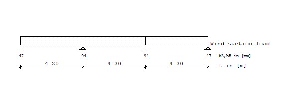
Loads Type 1: Trapezodial distributed load from a to a+b
Type 2: Pointload at a
Type 3: Temperature difference over full girder length
Dead load, snow, wind Load Type q1 Start q2 Length
[kN/m^2] [m] [kN/m^2] [m]
ws wind suction load 1 -1.750 0.000 -1.750 4.200
1 -1.750 4.200 -1.750 4.200
1 -1.750 8.400 -1.750 4.200
Temperature Service limit state (SLS) dT1
[°C]
tsu,sls temperature, summer 3 55.000
twi,sls temperature, winter - with snow - 3 -20.000
twi,sls temperature, winter 3 -40.000
Tension capacity of the connection elements, gamma_m= 1.33
End support Fz,d= Fz,k/gamma_m= 2.30/1.33= 1.73 kN/connection element
Internal support Fz,d= Fz,k/gamma_m= 2.30/1.33= 1.73 kN/connection element
Reaction at the supports, single load case excluding safety factors
Support V(d,uls) V(ws,uls) V(d,sls) V(ws,sls) V(tsu,sls) V(twi,sls)
[-] [kN/m] [kN/m] [kN/m] [kN/m] [kN/m] [kN/m]
1 0.330 -3.675 0.270 -3.004 1.168 -0.850
2 0.659 -7.350 0.720 -8.021 -1.168 0.850
3 0.659 -7.350 0.720 -8.021 -1.168 0.850
4 0.330 -3.675 0.270 -3.004 1.168 -0.850
Reaction at the supports, load combination including safety factors - reqired connection
elements rely on the module width, module width = 1.000 m
Load combination Support Vlfk req. n_con cho. n_con
[-] [kN/m] [-] [-]
1.0*G,t+1.5*Ws,t 1 -5.183 3 3
1.0*G,g+1.50*(Ws,g+0.6*Tso) 2 -12.363 7 6 ***
1.0*G,g+1.50*(Ws,g+0.6*Tso) 3 -12.363 7 6 ***
1.0*G,t+1.5*Ws,t 4 -5.183 3 3
The proof "Introduction of the shear load of the roof into the substructure" is not part
of this design and must be done subsequently!
6 Summary of design
Ultimate limit state (ULS)
sigma_w,mf 71.1 %
sigma_w,mst -
fcv 54.1 %
fcc 100.1 %
sigma_w,mf,cr 55.1 %
sigma_w,mst,cr -
fcv,cr 81.9 %
Serviceability limit state (SLS)
sigma_w,mf 49.8 %
sigma_w,mst 99.6 %
fcv 28.1 %
fcc 66.2 %
f 50.9 %
sigma_w,mf,cr 44.2 %
sigma_w,mst,cr 99.2 %
fcv,cr 35.0 %
f,cr 40.9 %