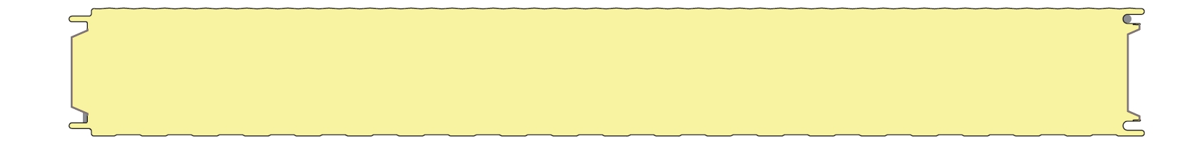
1 Panel specification Kingspan KS1150 NF 100 MQ according German approval Z-10.49-536
Cross section values per [m] of wall width
Outer sheet type M
Nominal thickness t_nom = 0.60 mm
Design thickness t_d = 0.54 mm
Cross sectional area A = 5.40 cm^2/m
Inner sheet type Q
Nominal thickness t_nom = 0.50 mm
Design thickness t_d = 0.44 mm
Cross sectional area A = 4.40 cm^2/m
Sandwich panel Design values for wrinkling stress
Element thickness = 100.0 mm
Outer sheet type M
Section modulus W_outside = 53.70 cm^3/m Serviceability limit state (SLS)
W_inside = 43.76 cm^3/m T <= 20°C T > 20°C
Moment of inertia I = 239.8 cm^4/m Sigma_w, field 174.0 MPa 158.0 MPa
Bending stiffness B = 503.6 kNm^2/m Sigma_w, support 122.0 MPa 111.0 MPa
Shear stiffness S = 296.7 kN/m
Ultimate limit state (ULS)
T <= 20°C T > 20°C
Sigma_w, field 174.0 MPa 158.0 MPa
Sigma_w, support 122.0 MPa 111.0 MPa
Material parameters
Steel cover sheets Inner sheet type Q
Modulus of elasticity E = 210000 MPa Serviceability limit state (SLS)
Yield strength fy = 280 MPa T <= 20°C T > 20°C
Sigma_w, field 152.0 MPa 152.0 MPa
Sigma_w, support 122.0 MPa 122.0 MPa
Foam core IPN3
Shear modulus Gs = 3.00 MPa Ultimate limit state (ULS)
Shear strength fcv = 0.110 MPa T <= 20°C T > 20°C
Compression strength fcc = 0.070 MPa Sigma_w, field 152.0 MPa 152.0 MPa
Sigma_w, support 122.0 MPa 122.0 MPa
2 Structural frame and loads
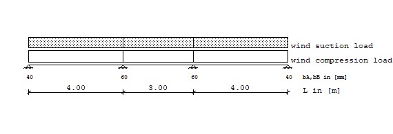
Loads Type 1: Trapezodial distributed load from a to a+b
Type 2: Pointload at a
Type 3: Temperature difference over full girder length
Wind Load Type q1 Start q2 Length
[kN/m^2] [m] [kN/m^2] [m]
wc wind compression load 1 0.400 0.000 0.400 4.000
1 0.400 4.000 0.400 3.000
1 0.400 7.000 0.400 4.000
ws wind suction load 1 -0.350 0.000 -0.350 4.000
1 -0.350 4.000 -0.350 3.000
1 -0.350 7.000 -0.350 4.000
Temperature Ultimate limit state (ULS) dT1
[°C]
tsu,uls temperature, summer 3 55.000
twi,uls temperature, winter 3 -40.000
Temperature Service limit state (SLS) dT1
[°C]
tsu,sls temperature, summer 3 55.000
twi,sls temperature, winter 3 -40.000
3 Inital forces and deflections
3.1 Ultimate limit state (ULS), a serie of simply supported panels
3.1.1 wc, wind compression load
Sagging moments / Deflections
Bay Mf Xmf f Xf
[-] [kNm/m] [m] [cm] [m]
1 0.800 2.00 0.533 2.00
2 0.450 1.50 0.235 1.50
3 0.800 2.00 0.533 2.00
Hogging moments / Reaction at the support
Support Mst Qle Qri V
[-] [kNm/m] [kN/m] [kN/m] [kN/m]
1 0.000 0.000 0.800 0.800
2 0.000 -0.800 0.600 1.400
3 0.000 -0.600 0.800 1.400
4 0.000 -0.800 0.000 0.800
3.1.2 ws, wind suction load
Sagging moments / Deflections
Bay Mf Xmf f Xf
[-] [kNm/m] [m] [cm] [m]
1 -0.700 2.00 -0.466 2.00
2 -0.394 1.50 -0.205 1.50
3 -0.700 2.00 -0.466 2.00
Hogging moments / Reaction at the support
Support Mst Qle Qri V
[-] [kNm/m] [kN/m] [kN/m] [kN/m]
1 0.000 0.000 -0.700 -0.700
2 0.000 0.700 -0.525 -1.225
3 0.000 0.525 -0.700 -1.225
4 0.000 0.700 0.000 -0.700
3.1.3 tsu, temperature summer
Sagging moments / Deflections
Bay Mf Xmf f Xf
[-] [kNm/m] [m] [cm] [m]
1 0.000 0.00 -1.320 2.00
2 0.000 0.00 -0.742 1.50
3 0.000 0.00 -1.320 2.00
Hogging moments / Reaction at the support
Support Mst Qle Qri V
[-] [kNm/m] [kN/m] [kN/m] [kN/m]
1 0.000 0.000 0.000 0.000
2 0.000 0.000 0.000 0.000
3 0.000 0.000 0.000 0.000
4 0.000 0.000 0.000 0.000
3.1.4 twi, temperature winter
Sagging moments / Deflections
Bay Mf Xmf f Xf
[-] [kNm/m] [m] [cm] [m]
1 0.000 0.00 0.960 2.00
2 0.000 0.00 0.540 1.50
3 0.000 0.00 0.960 2.00
Hogging moments / Reaction at the support
Support Mst Qle Qri V
[-] [kNm/m] [kN/m] [kN/m] [kN/m]
1 0.000 0.000 0.000 0.000
2 0.000 0.000 0.000 0.000
3 0.000 0.000 0.000 0.000
4 0.000 0.000 0.000 0.000
3.2 Serviceability limit state (SLS), multi-span panel
3.2.1 wc, wind compression load - normal temperature -
Sagging moments / Deflections
Bay Mf Xmf f Xf
[-] [kNm/m] [m] [cm] [m]
1 0.582 0.00 0.440 0.00
2 -0.020 0.00 0.131 0.00
3 0.582 0.00 0.440 0.00
Hogging moments / Reaction at the support
Support Mst Qle Qri V
[-] [kNm/m] [kN/m] [kN/m] [kN/m]
1 0.000 0.000 0.684 0.684
2 -0.466 -0.916 0.600 1.516
3 -0.466 -0.600 0.916 1.516
4 0.000 -0.684 0.000 0.684
3.2.2 ws, wind suction load - normal temperature -
Sagging moments / Deflections
Bay Mf Xmf f Xf
[-] [kNm/m] [m] [cm] [m]
1 -0.510 1.80 -0.385 2.00
2 0.018 1.35 -0.114 1.50
3 -0.510 2.20 -0.385 2.00
Hogging moments / Reaction at the support
Support Mst Qle Qri V
[-] [kNm/m] [kN/m] [kN/m] [kN/m]
1 0.000 0.000 -0.598 -0.598
2 0.408 0.802 -0.525 -1.327
3 0.408 0.525 -0.802 -1.327
4 0.000 0.598 0.000 -0.598
3.2.3 tsu, temperature summer
Sagging moments / Deflections
Bay Mf Xmf f Xf
[-] [kNm/m] [m] [cm] [m]
1 3.573 4.00 -0.631 0.00
2 3.573 0.00 0.056 0.00
3 3.573 0.00 -0.631 0.00
Hogging moments / Reaction at the support
Support Mst Qle Qri V
[-] [kNm/m] [kN/m] [kN/m] [kN/m]
1 0.000 0.000 0.893 0.893
2 3.573 0.893 0.000 -0.893
3 3.573 0.000 -0.893 -0.893
4 0.000 -0.893 0.000 0.893
3.2.4 twi, temperature winter
Sagging moments / Deflections
Bay Mf Xmf f Xf
[-] [kNm/m] [m] [cm] [m]
1 -2.599 4.00 0.459 1.60
2 -2.599 0.00 -0.041 1.50
3 -2.599 0.00 0.459 2.40
Hogging moments / Reaction at the support
Support Mst Qle Qri V
[-] [kNm/m] [kN/m] [kN/m] [kN/m]
1 0.000 0.000 -0.650 -0.650
2 -2.599 -0.650 0.000 0.650
3 -2.599 0.000 0.650 0.650
4 0.000 0.650 0.000 -0.650
4 Design of sandwich panel
4.1 Ultimate limit state (ULS)
4.1.1 Limited normal stresses in face layers: Bay
gamma_m,sigma_w(outer shell)= 1.20 gamma_m,sigma_w(inner shell)= 1.20 gamma_m,fy= 1.10
Load combination Bay Sigma,o Sigma_w,o util. Sigma,i Sigma_w,i Util.
[-] [-] [MPa] [MPa] [-] [MPa] [MPa] [-]
1.50*Wc 1 -22.3 < 131.7 0.170 27.4 < 254.5 0.108
2 -12.6 < 131.7 0.095 15.4 < 254.5 0.061
3 -22.3 < 131.7 0.170 27.4 < 254.5 0.108
1.50*Ws 1 19.6 < 254.5 0.077 -24.0 < 126.7 0.189
2 11.0 < 254.5 0.043 -13.5 < 126.7 0.107
3 19.6 < 254.5 0.077 -24.0 < 126.7 0.189
4.1.2 Limited shear stress in the core material: gamma_m= 1.37
Load combination Support Tau fcv Util.
[-] [-] [MPa] [MPa] [-]
1.50*Wc 1 0.012 < 0.080 0.151
2 0.012 < 0.080 0.151
3 0.012 < 0.080 0.151
4 0.012 < 0.080 0.151
1.50*Ws 1 0.011 < 0.080 0.132
2 0.011 < 0.080 0.132
3 0.011 < 0.080 0.132
4 0.011 < 0.080 0.132
4.1.3 Compression stresses at support, support widths: gamma_m= 1.26
Load combination Support Al Req b Exist b Util.
[-] [kN/m] [mm] [mm] [-]
1.50*Wc 1 1.200 21.6 < 40.0 0.540
2 2.100 37.8 < 60.0 0.630
3 2.100 37.8 < 60.0 0.630
4 1.200 21.6 < 40.0 0.540
4.2 Serviceability limit state (SLS)
4.2.1 Limited normal stresses in face layers: Bay
gamma_m,sigma_w(outer shell)= 1.05 gamma_m,sigma_w(inner shell)= 1.05 gamma_m,fy= 1.00
Load combination Bay Sigma,o Sigma_w,o util. Sigma,i Sigma_w,i Util.
[-] [-] [MPa] [MPa] [-] [MPa] [MPa] [-]
1.0*Wc+0.6*Twi 1 -2.0 < 165.7 0.012 2.4 < 280.0 0.009
2 without design
3 -2.0 < 165.7 0.012 2.4 < 280.0 0.009
0.6*Wc+1.0*Twi 1 without design
2 without design
3 without design
1.0*Ws+0.6*Tsu 1 0.1 < 280.0 0.000 -0.1 < 144.8 0.001
2 without design
3 0.1 < 280.0 0.000 -0.1 < 144.8 0.001
0.6*Ws+1.0*Tsu 1 without design
2 without design
3 without design
1.0*Wc+0.6*Tsu 1 -34.6 < 150.5 0.230 42.5 < 280.0 0.152
2 -39.6 < 150.5 0.263 48.6 < 280.0 0.174
3 -34.6 < 150.5 0.230 42.5 < 280.0 0.152
0.6*Wc+1.0*Tsu 1 without design
2 -66.4 < 150.5 0.441 81.4 < 280.0 0.291
3 without design
1.0*Ws+0.6*Twi 1 26.0 < 280.0 0.093 -31.9 < 144.8 0.220
2 28.8 < 280.0 0.103 -35.3 < 144.8 0.244
3 26.0 < 280.0 0.093 -31.9 < 144.8 0.220
0.6*Ws+1.0*Twi 1 without design
2 48.2 < 280.0 0.172 -59.2 < 144.8 0.409
3 without design
4.2.2 Limited normal stresses in face layers: Support
gamma_m,sigma_w(outer shell)= 1.05 gamma_m,sigma_w(inner shell)= 1.05 gamma_m,fy= 1.00
Load combination Support Sigma,o Sigma_w,o Util. Sigma,i Sigma_w,i Util.
[-] [-] [MPa] [MPa] [-] [MPa] [MPa] [-]
1.0*Tsu 2 -66.5 < 105.7 0.629 81.7 < 280.0 0.292
3 -66.5 < 105.7 0.629 81.7 < 280.0 0.292
1.0*Twi 2 48.4 < 280.0 0.173 -59.4 < 116.2 0.511
3 48.4 < 280.0 0.173 -59.4 < 116.2 0.511
1.0*Wc+0.6*Twi 2 37.7 < 280.0 0.135 -46.3 < 116.2 0.398
3 37.7 < 280.0 0.135 -46.3 < 116.2 0.398
0.6*Wc+1.0*Twi 2 53.6 < 280.0 0.191 -65.8 < 116.2 0.566
3 53.6 < 280.0 0.191 -65.8 < 116.2 0.566
1.0*Ws+0.6*Tsu 2 -47.5 < 105.7 0.449 58.3 < 280.0 0.208
3 -47.5 < 105.7 0.449 58.3 < 280.0 0.208
0.6*Ws+1.0*Tsu 2 -71.1 < 105.7 0.673 87.3 < 280.0 0.312
3 -71.1 < 105.7 0.673 87.3 < 280.0 0.312
1.0*Wc+0.6*Tsu 2 -31.3 < 105.7 0.296 38.3 < 280.0 0.137
3 -31.3 < 105.7 0.296 38.3 < 280.0 0.137
0.6*Wc+1.0*Tsu 2 -61.3 < 105.7 0.580 75.3 < 280.0 0.269
3 -61.3 < 105.7 0.580 75.3 < 280.0 0.269
1.0*Ws+0.6*Twi 2 21.4 < 280.0 0.077 -26.3 < 116.2 0.227
3 21.4 < 280.0 0.077 -26.3 < 116.2 0.227
0.6*Ws+1.0*Twi 2 43.8 < 280.0 0.157 -53.8 < 116.2 0.463
3 43.8 < 280.0 0.157 -53.8 < 116.2 0.463
4.2.3 Limited shear stress in the core material: gamma_m= 1.10
Load combination Support Tau fcv Util.
[-] [-] [MPa] [MPa] [-]
1.0*Tsu 1 0.009 < 0.100 0.090
2 0.009 < 0.100 0.090
3 0.009 < 0.100 0.090
4 0.009 < 0.100 0.090
1.0*Twi 1 0.007 < 0.100 0.066
2 0.007 < 0.100 0.066
3 0.007 < 0.100 0.066
4 0.007 < 0.100 0.066
1.0*Wc+0.6*Twi 1 0.003 < 0.100 0.030
2 0.013 < 0.100 0.132
3 0.013 < 0.100 0.132
4 0.003 < 0.100 0.030
0.6*Wc+1.0*Twi 1 0.002 < 0.100 0.024
2 0.012 < 0.100 0.121
3 0.012 < 0.100 0.121
4 0.002 < 0.100 0.024
1.0*Ws+0.6*Tsu 1 0.001 < 0.100 0.006
2 0.014 < 0.100 0.135
3 0.014 < 0.100 0.135
4 0.001 < 0.100 0.006
0.6*Ws+1.0*Tsu 1 0.005 < 0.100 0.054
2 0.014 < 0.100 0.139
3 0.014 < 0.100 0.139
4 0.005 < 0.100 0.054
1.0*Wc+0.6*Tsu 1 0.012 < 0.100 0.123
2 0.006 < 0.100 0.061
3 0.006 < 0.100 0.061
4 0.012 < 0.100 0.123
0.6*Wc+1.0*Tsu 1 0.013 < 0.100 0.132
2 0.004 < 0.100 0.036
3 0.004 < 0.100 0.036
4 0.013 < 0.100 0.132
1.0*Ws+0.6*Twi 1 0.010 < 0.100 0.100
2 0.005 < 0.100 0.053
3 0.005 < 0.100 0.053
4 0.010 < 0.100 0.100
0.6*Ws+1.0*Twi 1 0.010 < 0.100 0.102
2 0.003 < 0.100 0.032
3 0.003 < 0.100 0.032
4 0.010 < 0.100 0.102
4.2.4 Compression stresses at support, support widths: gamma_m= 1.07
Load combination Support Al Req b Exist b Util.
[-] [kN/m] [mm] [mm] [-]
1.0*Tsu 1 0.893 13.7 < 40.0 0.341
4 0.893 13.7 < 40.0 0.341
1.0*Twi 2 0.650 9.9 < 60.0 0.166
3 0.650 9.9 < 60.0 0.166
1.0*Wc+0.6*Twi 1 0.294 4.5 < 40.0 0.112
2 1.906 29.1 < 60.0 0.486
3 1.906 29.1 < 60.0 0.486
4 0.294 4.5 < 40.0 0.112
0.6*Wc+1.0*Twi 2 1.560 23.8 < 60.0 0.397
3 1.560 23.8 < 60.0 0.397
0.6*Ws+1.0*Tsu 1 0.535 8.2 < 40.0 0.204
4 0.535 8.2 < 40.0 0.204
1.0*Wc+0.6*Tsu 1 1.220 18.6 < 40.0 0.466
2 0.980 15.0 < 60.0 0.250
3 0.980 15.0 < 60.0 0.250
4 1.220 18.6 < 40.0 0.466
0.6*Wc+1.0*Tsu 1 1.303 19.9 < 40.0 0.498
2 0.017 0.3 < 60.0 0.004
3 0.017 0.3 < 60.0 0.004
4 1.303 19.9 < 40.0 0.498
4.2.5 Deflections: gamma_m= 1.0
Load combination Bay f Perm. f, L/100 Util.
[-] [-] [cm] [cm] [-]
1.0*Tsu 1 -0.631 < 4.000 0.158
2 0.056 < 3.000 0.019
3 -0.631 < 4.000 0.158
1.0*Twi 1 0.459 < 4.000 0.115
2 -0.041 < 3.000 0.014
3 0.459 < 4.000 0.115
1.0*Wc 1 0.440 < 4.000 0.110
2 0.131 < 3.000 0.044
3 0.440 < 4.000 0.110
1.0*Ws 1 -0.385 < 4.000 0.096
2 -0.114 < 3.000 0.038
3 -0.385 < 4.000 0.096
0.75*Wc0.6*1.0*Twi 1 0.606 < 4.000 0.151
2 0.074 < 3.000 0.025
3 0.606 < 4.000 0.151
0.6*0.75*Wc+1.0*Twi 1 0.657 < 4.000 0.164
2 0.018 < 3.000 0.006
3 0.657 < 4.000 0.164
0.75*Ws+0.6*1.0*Tsu 1 -0.668 < 4.000 0.167
2 -0.052 < 3.000 0.017
3 -0.668 < 4.000 0.167
0.6*0.75*Wc+1.0*Tsu 1 -0.805 < 4.000 0.201
2 0.004 < 3.000 0.001
3 -0.805 < 4.000 0.201
5.1 Design of connection elements
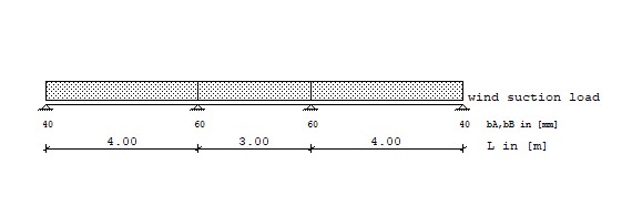
Loads Type 1: Trapezodial distributed load from a to a+b
Type 2: Pointload at a
Type 3: Temperature difference over full girder length
Wind Load Type q1 Start q2 Length
[kN/m^2] [m] [kN/m^2] [m]
ws wind suction load 1 -0.350 0.000 -0.350 4.000
1 -0.350 4.000 -0.350 3.000
1 -0.350 7.000 -0.350 4.000
Temperature Service limit state (SLS) dT1
[°C]
tsu,sls temperature, summer 3 55.000
twi,sls temperature, winter 3 -40.000
Tension capacity of the connection elements, gamma_m= 1.33
End support Fz,d= Fz,k/gamma_m= 2.30/1.33= 1.73 kN/connection element
Internal support Fz,d= Fz,k/gamma_m= 2.30/1.33= 1.73 kN/connection element
Reaction at the supports, single load case excluding safety factors
Support V(ws,uls) V(wc,sls) V(ws,sls) V(tsu,sls) V(twi,sls)
[-] [kN/m] [kN/m] [kN/m] [kN/m] [kN/m]
1 -0.700 0.684 -0.598 0.893 -0.650
2 -1.225 1.516 -1.327 -0.893 0.650
3 -1.225 1.516 -1.327 -0.893 0.650
4 -0.700 0.684 -0.598 0.893 -0.650
Reaction at the supports, load combination including safety factors - reqired connection
elements rely on the module width, module width = 1.150 m
Load combination Support Vlfk req. n_con cho. n_con
[-] [kN/m] [-] [-]
1.50*(0.6*Ws,sls+1.0*Twi) 1 -1.513 2 2
1.50*(1.0*Ws,sls+0.6*Tsu) 2 -2.794 2 2
1.50*(1.0*Ws,sls+0.6*Tsu) 3 -2.794 2 2
1.50*(0.6*Ws,sls+1.0*Twi) 4 -1.513 2 2
The proof "Introduction of the dead load of the wall into the substructure" is not part
of this design and must be done subsequently!
6 Summary of design
Ultimate limit state (ULS)
sigma_w,f 18.9 %
sigma_w,st -
fcv 15.1 %
fcc 63.0 %
Serviceability limit state (SLS)
sigma_w,f 44.1 %
sigma_w,st 67.3 %
fcv 13.9 %
fcc 49.8 %
f 20.1 %