 Hacierco 135/310
1 Section properties of the trapezoidal sheet in compliance with
baustatische Typenprüfung Bescheid Nr. T18-056
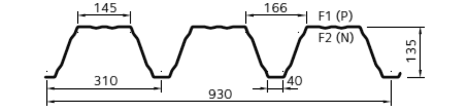
Hacierco 135/310
broad flange in compression
Nominal thickness = 0.88 mm Design thickness = 0.84 mm
Dead load g = 0.106 kN/m^2 Yield strength fy,k = 350 N/mm^2
Effective Properties of section
Properties of section for bending: Ief+ = 317.2 cm^4/m Ief- = 314.2 cm^4/m
Properties of section for axial force: Ag = 13.26 cm^2/m ig = 4.91 cm zg = 8.23 cm
Aef = 5.50 cm^2/m ief = 5.78 cm zef = 8.04 cm
Characteristic capacity of the trapezoidal sheet for UDL downwards
Width of the end support bA = 40 mm Width of the internal support bB = 60 mm eps = 2
Mc,Rk,F = 13.83 kNm/m Rw,Rk,A = 11.56 kN/m Vw,Rk = 45.75 kN/m
M0,Rk,B = 15.10 kNm/m R0,Rk,B = 30.43 kN/m Mc,Rk,B = 10.95 kNm/m Rw,Rk,B = 25.99 kN/m
minL = 5.07 m maxL = 5.80 m maxMR,Rk = 2.66 kNm/m
Width of the end support bA = 40 mm Width of the internal support bB = 160 mm eps = 2
Mc,Rk,F = 13.83 kNm/m Rw,Rk,A = 11.56 kN/m Vw,Rk = 45.75 kN/m
M0,Rk,B = 14.81 kNm/m R0,Rk,B = 43.41 kN/m Mc,Rk,B = 12.65 kNm/m Rw,Rk,B = 36.00 kN/m
minL = 5.88 m maxL = 6.39 m maxMR,Rk = 2.78 kNm/m
Characteristic capacity of the trapezoidal sheet for UDL upwards
Connection to every flange eps = 1
Mc,Rk,F = 11.59 kNm/m Rw,Rk,A = 45.75 kN/m Vw,Rk = 45.75 kN/m
M0,Rk,B = 17.29 kNm/m R0,Rk,B = 0.00 kN/m Mc,Rk,B = 13.83 kNm/m Rw,Rk,B = 0.00 kN/m
Connection to every second flange eps = 1
Mc,Rk,F = 11.59 kNm/m Rw,Rk,A = 22.88 kN/m Vw,Rk = 22.88 kN/m
M0,Rk,B = 8.64 kNm/m R0,Rk,B = 0.00 kN/m Mc,Rk,B = 6.92 kNm/m Rw,Rk,B = 0.00 kN/m
Symbols (elements of capacity)
Mc,Rk,F Sagging moment capacity maxMR,Rk residual moment capacity
Rw,Rk,A External support capacity Vw,Rk Shear force
M0,Rk,B Hogging moment capacity under the assumption of no shear force
R0,Rk,B Internal support capacity under the assumption of no moment
Mc,Rk,B Hogging moment capacity Rw,Rk,B Internal support capacity
eps 1: linear interaction for M and R 2: quadratic interaction for M and R
2 Structural system and loads
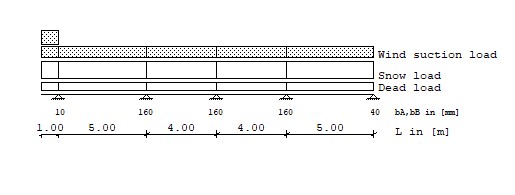
Loads Type 1: Trapezodial distributed load from a to a+b
Type 2: Pointload at a
Load Type q1 Start q2 Length
[kN/m^2] [m] [kN/m^2] [m]
g Dead load 1 0.350 0.000 0.350 1.000
1 0.350 1.000 0.350 5.000
1 0.350 6.000 0.350 4.000
1 0.350 10.000 0.350 4.000
1 0.350 14.000 0.350 5.000
s Snow load 1 0.750 0.000 0.750 1.000
1 0.750 1.000 0.750 5.000
1 0.750 6.000 0.750 4.000
1 0.750 10.000 0.750 4.000
1 0.750 14.000 0.750 5.000
ws Wind suction load 1 -0.480 0.000 -0.480 1.000
1 -0.600 0.000 -0.600 1.000
1 -0.480 1.000 -0.480 5.000
1 -0.480 6.000 -0.480 4.000
1 -0.480 10.000 -0.480 4.000
1 -0.480 14.000 -0.480 5.000
3 Design of trapezoidal sheets in compliance with Building Standard "EN 1993-1-3 (EC3)"
3.1 Ultimate limit state (ULS) elastic-elastic
3.1.1 Sagging moment gamma-F,G= 1.35 gamma-F,Q= 1.50 gamma-M= 1.10
Load combination Bay MEd Mc,Rd,F Utilization
[-] [-] [kNm/m] [kNm/m] [-]
1.35*G+1.50*S 1 2.855 < 12.573 0.227
2 0.815 < 12.573 0.065
3 0.726 < 12.573 0.058
4 3.231 < 12.573 0.257
1.00*G+1.50*Ws 1 -0.479 < 10.536 0.045
2 -0.224 < 10.536 0.021
3 -0.150 < 10.536 0.014
4 -0.751 < 10.536 0.071
3.1.2 Reaction at end support gamma-F,G= 1.35 gamma-F,Q= 1.50 gamma-M= 1.10
Load combination Support FEd Rw,Rd,A Utilization
[-] [kN/m] [kN/m] [-]
1.35*G+1.50*S 5 3.213 < 10.509 0.306
1.00*G+1.50*Ws 5 -0.746 < 20.795 0.036
3.1.3 Shear force at internal support gamma-F,G= 1.35 gamma-F,Q= 1.50 gamma-M= 1.10
Load combination Support VEd Vw,Rd bv Utiliz.
[-] [kN/m] [kN/m] [-] [-]
1.35*G+1.50*S 1 3.417 < 41.591 0.363 0.082
1.35*G+1.50*S 2 -4.571 < 41.591 0.093 0.110
1.35*G+1.50*S 3 -2.599 < 41.591 0.011 0.062
1.35*G+1.50*S 4 4.775 < 41.591 0.108 0.115
1.00*G+1.50*Ws 1 1.270 < 20.795 0.166 0.061
1.00*G+1.50*Ws 2 0.942 < 20.795 0.060 0.045
1.00*G+1.50*Ws 3 0.644 < 20.795 0.035 0.031
1.00*G+1.50*Ws 4 -1.104 < 20.795 0.113 0.053
bv > 0.20, it will be calculated with reduced support widths (DIN EN 1993-1-3, 6.1.7.3).
3.1.4 Reaction at internal support gamma-F,G= 1.35 gamma-F,Q= 1.50 gamma-M= 1.10
Load combination Support FEd Rw,Rd,B Utilization
[-] [kN/m] [kN/m] [-]
1.35*G+1.50*S 1 5.014 < 13.770 0.364
1.35*G+1.50*S 2 8.362 < 32.727 0.256
1.35*G+1.50*S 3 5.142 < 32.727 0.157
1.35*G+1.50*S 4 8.622 < 32.727 0.263
1.00*G+1.50*Ws Design not necessary!
3.1.5 Hogging moment gamma-F,G= 1.35 gamma-F,Q= 1.50 gamma-M= 1.10
Load combination Support MEd Mc,Rd,B Utilization
[-] [kNm/m] [kNm/m] [-]
1.35*G+1.50*S 1 -0.799 < 5.801 0.138
2 -3.683 < 11.500 0.320
3 -1.298 < 11.500 0.113
4 -3.905 < 11.500 0.340
1.00*G+1.50*Ws 1 0.635 < 6.286 0.101
2 0.720 < 6.286 0.115
3 0.336 < 6.286 0.053
4 0.897 < 6.286 0.143
3.1.6 Combined check for bending and reaction gamma-F,G= 1.35 gamma-F,Q= 1.50 gamma-M= 1.10
Load combination Support MEd/M0,Rd,B + (FEd/R0,Rd,B)^eps Utiliz.
[-] [-] [-] [-]
1.35*G+1.50*S 1 0.100 + 0.097 0.197
2 0.274 + 0.045 0.318
3 0.096 + 0.017 0.113
4 0.290 + 0.048 0.338
1.00*G+1.50*Ws Design not necessary!
3.1.7 Combined check for bending and shear gamma-F,G= 1.35 gamma-F,Q= 1.50 gamma-M= 1.10
Load combination Support MEd/Mc,Rd,B + (2*VEd/V,Rd,B-1)^2
[-] [-] [-] [-]
1.35*G+1.50*S Design not necessary!
1.00*G+1.50*Ws Design not necessary!
3.2 Serviceability limit state (SLS) elastic - elastic
3.2.1 Deflection gamma-F,G= 1.00 gamma-F,Q= 1.00 gamma-M= 1.00
Load combination Bay f Perm. f, L/300 Utilization
[-] [-] [cm] [cm] [-]
1.00*G+1.00*S 1 0.627 < 1.667 0.376
2 0.046 < 1.333 0.035
3 -0.053 < 1.333 0.040
4 0.724 < 1.667 0.434
Cant-le -0.385 < 0.667
1.00*G+1.00*Ws 1 -0.026 < 1.667 0.016
2 -0.014 < 1.333 0.011
3 0.008 < 1.333 0.006
4 -0.090 < 1.667 0.054
Cant-le -0.029 < 0.667
3.3 Maximum span during construction
Bay Span Maximum span Utilization
[-] [m] [m] [-]
1 5.000 < 12.500 0.400
2 4.000 < 12.500 0.320
3 4.000 < 12.500 0.320
4 5.000 < 12.500 0.400
The design of the trapezoidal sheet is ok. The load capacities of trapezoidal profiles can
have large differences from manufacturer to manufacturer. Therefore, it is important that
the trapezoidal profile listed herein is actually installed on-site during construction.
4 Design of connection elements
4.1 Connection to the construction below
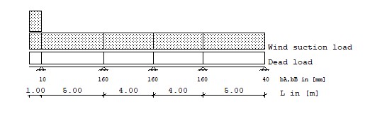
Loads Type 1: Trapezodial distributed load from a to a+b
Type 2: Pointload at a
Load Type q1 Start q2 Length
[kN/m^2] [m] [kN/m^2] [m]
Ws, wind suction load 1 -0.480 0.000 -0.480 1.000
1 -0.600 0.000 -0.600 1.000
1 -0.480 1.000 -0.480 5.000
1 -0.480 6.000 -0.480 4.000
1 -0.480 10.000 -0.480 4.000
1 -0.480 14.000 -0.480 5.000
Characteristic forces of connection elements:
End support Fz,k= 3.600 kN VR,k= 3.600 kN
Internal support Fz,k= 3.600 kN VR,k= 3.600 kN
Shear and tension capacity of the connection elements, gamma= 1.33:
End support Fz,d= 2.707 kN Fq,d= 2.707 kN
Internal support Fz,d= 2.707 kN Fq,d= 2.707 kN
Reaction at the support, load case excluding safety factors:
Support Rv,k(g) Rv,k(s) Rv,k(wd) Rv,k(ws) Rv,k(opt.) Descript. Rh,k(opt.) Descript.
[-] [kN/m] [kN/m] [kN/m] [kN/m] [kN/m] [-] [kN/m] [-]
1 1.099 2.354 0.000 -2.184 0.000 0.000
2 1.832 3.926 0.000 -2.407 0.000 0.000
3 1.127 2.414 0.000 -1.580 0.000 0.000
4 1.889 4.048 0.000 -2.582 0.000 0.000
5 0.704 1.508 0.000 -0.966 0.000 0.000
Reaction at support for load combinations:
Load combination Support Vertical Horizontal
[-] [kN/m] [kN/m]
0.9*G+1.5*Ws 1 -2.288 0.000
0.9*G+1.5*Ws 2 -1.961 0.000
0.9*G+1.5*Ws 3 -1.356 0.000
0.9*G+1.5*Ws 4 -2.173 0.000
0.9*G+1.5*Ws 5 -0.816 0.000
Design check for connecting elements
Support nVerb nbR NE,d NR,d VE,d VR,d Utilization
[-] [-] [-] [kN] [kN] [kN] [kN] [-]
1 1 1 0.709 < 2.707 0.000 < 2.707 0.262
2 1 2 1.216 < 2.707 0.000 < 2.707 0.449
3 1 2 0.841 < 2.707 0.000 < 2.707 0.311
4 1 2 1.348 < 2.707 0.000 < 2.707 0.498
5 1 1 0.253 < 2.707 0.000 < 2.707 0.093
Rv, Rh : Reaction at support caused by load combinations
nVerb : Number of connecting elements
nbR : 1 = Connection element at every trough
2 = Connection element at every second trough
bR : Module width
NE,d : Applied tension force in the connecting element = Rv·1/nVerb·bR·(-1)
NR,d : Tension capacity in the connecting element
VE,d : Applied shear force in the connecting element = Rh·1/nVerb·bR
VR,d : Shear capacity in the connecting element
5 Summary of design
Ultimate limit state (ULS) elastic-elastic
Mc,Rk,f 25.7 %
Rw,Rk,A 30.6 %
Rw,Rk,B 36.4 %
Vw,Rk 11.5 %
Mc,Rk,B 34.0 %
M-R 33.8 %
Ultimate limit state (ULS) plastic-plastic
Mc,Rk,f -
Rw,Rk,A -
Serviceability limit state (SLS) elastic - elastic
Rw,Rk,B -
Mc,Rk,B -
M-R -
f 43.4 %